Curvo Studio

Semiconductor simulators

Semiconductors control current without moving parts. This group contains the PN junction diode, the Zener diode, the LED, the NPN bipolar junction transistor (BJT), the N-channel enhancement MOSFET and the operational amplifier. Each simulator plots the characteristic curves you would find in a datasheet and marks the live operating point on them. Sweep the forward voltage of a diode and watch the knee appear, push a Zener into breakdown, pick an LED colour and set its series resistor, bias a BJT or MOSFET from cutoff into saturation, or close the feedback loop around an op-amp and see gain and clipping. Temperature, threshold voltage and supply rails can all be adjusted in the browser. Begin with the PN diode, then move on to the transistors once the curve feels familiar.

6 interactive models
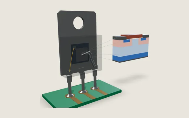
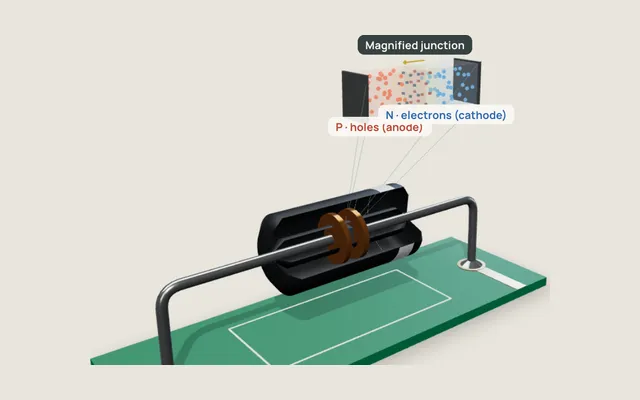
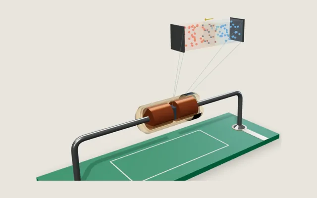
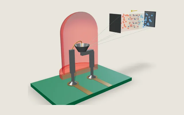
N-channel MOSFETSee how gate voltage creates a conductive channel and controls drain current between source and drain.Open simulator P–N junction diodeSee how the depletion region enables forward current, blocks reverse current and changes during breakdown.Open simulator Zener diodeSee how a Zener diode is built to survive reverse breakdown on purpose — once the knee is reached, the voltage across it barely moves even as the current swings.Open simulator LEDSwitch between real LED colors and watch why the current, not the voltage, is what you actually control — and why a bare LED on a supply is always one step from burning out.Open simulator
New
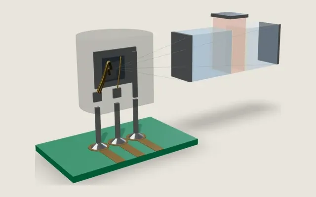
NPN transistorSee how a small base current controls a much larger collector current, and how the transistor moves from cutoff through the active region into saturation.Open simulator
New
Operational amplifierSet the feedback resistors and watch how gain, clipping at the supply rails, bandwidth and slew rate shape the amplified signal.Open simulator

Diagram symbol system: IEC 60617-inspired technical notation